Table Of Content
Companies should consider hiring experienced designers and engineers to design and build molds. The condition of a mold determines the success of the whole molding process and whether the product will have defects or will be perfectly produced. Before buying or creating a mold, some considerations need to be taken into account. Download this report for a step by step guide on 3D printed tooling for silicone part production, with mold design best practices and customer case studies.
Techni-Mold & Engineering, Inc. is expanding and adding new talent to its team
Examples of projects and molds manufactured by students include UMass Lowell-themed gadgets, toys and other fun and useful parts. Silicone casting is one of the most popular processes that leverage molds. Product developers, engineers, DIY makers, and even chefs all make silicone molds to create one-off or smaller runs of parts from plastics and a variety of other materials. Silicone is a strong choice for mold-making because it can be used to easily create custom designs and the molds themselves are also quite durable, so you can use them repeatedly without fear of breakage. Fulfilling these expectations depends on designing the best tooling option for each customer’s needs.
Common injection molding defects
Both gate styles generally can decrease the size of the vestige left on the exterior of the part. Tunnel gates still enter the part externally, but are mid-way down a parts surface, so they typically leave less of a gate vestige. Post gates leave no visible vestige on the exterior of the part as the part fills through one of the ejector pins close to the perimeter of the part.
Ready to Get Your Custom Mold Design Quotes?
There are tens of thousands of different materials available for injection molding. Most polymers may be used, including all thermoplastics (such as nylon, polyethylene, and polystyrene) and some elastomers. Materials are chosen based on the strength and function required for the final part, but each material also has different parameters for molding that must be considered.
By Design: Part design 304 - Depth of holes - PlasticsToday
By Design: Part design 304 - Depth of holes.
Posted: Thu, 30 Nov 2023 05:26:07 GMT [source]
The piece is then ejected from the mold, either as the final product or as a near-final product that is sent on for secondary finishing. 5.Due to the large size of the ejector pin fixing plate and the backing plate, the span between the movable mold backing plate is enlarged. 3.The relationship between the top of the ejector pin and the plane of the core (or cavity) should theoretically be on the same plane, which is convenient for mold manufacturing and assembly.
Matrix Tools and Solutions improves quality and reduces design time with Siemens’ solutions
The first aspect of a study may be to review the part design for features that may require complicated mold actions and to offer suggestions on how to improve the design and reduce the mold cost. Another benefit to the Tooling Feasibility Study is to send the study along with mold RFQ’s so that all potential vendors are quoting the same set of standards. If there are no good options for locating a gate on the outer cosmetic surface, reverse ejection may be considered — it should be the last option but may be the only choice.
Guides
Think Process Not FeaturesAll too often, companies invest in a new technology just to find out that their new “toy” merely moved their production bottlenecks from one stage of the process to another. To really make a difference in business outcomes, companies must first establish a streamlined process that covers all deliverables and milestones— from the initial price quotation to the finished product. Inputs and outputs for each step in the process need to be clearly identified, along with quality expectations and the value added to the finished product. Once the entire process has been laid out, specific technologies and methods can be considered based on their impact on the process outcome, not the latest bells and whistles. Injection molding engineering core includes ejection system design, gate design, runner design, cooling system design, and wall thickness. Most plastics manufactured currently are through injection mold making technology since the process permits affordable mass production of products at a lowered period.
As the name indicates, this gate is located on the edge of the part and is best suited for flat parts. Edge gates are ideal for medium and thick sections and can be used on multicavity two plate tools. While some stresses in an injection molded part are to be expected, you should design your parts with as much consideration for stress reduction as possible. Some ways to do this are by adding smooth transitions between features and using rounds and fillets in possible high stress areas.
The manufacturing & design guide
Our mold design procedure overlaps with our clients' product design most of the time. Having a strong knowledge of plastic component design is critical to the longterm success of the manufacturing process and finished product. The minimum wall thickness that can be used depends on the size and geometry of the part, structural requirements, and flow behavior of the resin. The wall thicknesses of an injection molded part generally range from 2mm – 4mm (0.080" – 0.160").
Other companies trying to beat a deadline may select a tool vendor quickly, hoping “things turn out right.” Typically, however, lack of due diligence leads to oversights or cut corners that take much longer to straighten out. Although rushing might get the first shots completed quickly, chances are the final submittal won’t be any faster. Detailed tool drawings are completed and construction standards are reviewed and verified. The tool builder’s progress is closely monitored and on-site meetings are held.
Through this pandemic, we have learned new approaches to teaching mold design that we would not have had the opportunity to explore under normal circumstances. The virtual delivery of lectures and lab activities, offered through video recording technology, allowed us to provide students the same practical demonstrations and real-world examples that we would typically use in class. This included video lectures on theory, examples of real molds and components and demonstrations of machining operations. Similarly, software tools typically taught in a computer lab were instead taught in a series of application-specific video tutorials. We specialize in mold designs, mold making, 3D printing, product design, CNC machining, over-molding, insert molding, and injection molding.
Keep these factors in mind when designing your injection molded part, and remember that it is easier to avoid problems in the beginning than change your design down the line. A parting line is the line of separation on the part where the two halves of the mold meet. The line actually indicates the parting "plane" that passes through the part. While on simple parts this plane can be a simple, flat surface, it is often a complex form that traces the perimeter of the part around the various features that make up the part’s outer silhouette.
3D Printing Slashes Unilever Bottle Design Costs - PlasticsToday
3D Printing Slashes Unilever Bottle Design Costs.
Posted: Mon, 25 Mar 2024 07:00:00 GMT [source]
Applying draft and radii to a part is vital to a properly designed injection-molded part. Draft helps a part release from a mold with less drag on the part's surface since the material shrinks onto the mold core. Limited draft requires an excessive amount of pressure on the ejection system that may damage parts and possibly the mold. Some are first prototyped through 3D printing where moldability considerations are of limited concern. Others take a more traditional machining route that allows for iterative testing in engineering-grade materials similar to that of molding. Further, instructors evaluate students based on technical presentations they deliver as a team in front of the whole class.
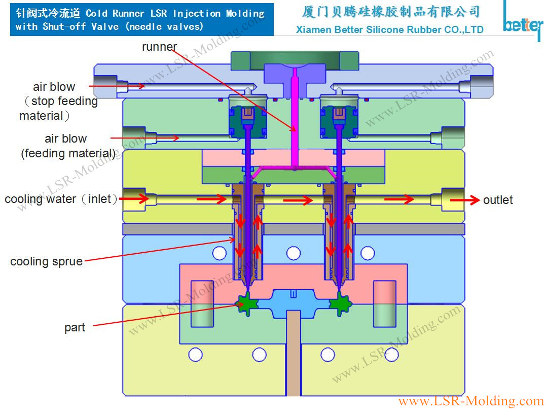
The most fundamental knowledge needed for any designer faced with designing an injection molded part is understanding the basics of mold (also referred to as tool) design. The remainder of this article will discuss the interrelationships between injection molding tool design and part design. During the injection molding process molten plastic flows through channels called “runners” into the mold cavity. The direction of flow is controlled by the “gate” at the end of each channel. The system of runners and gates must be carefully designed to assure even distribution of plastic and subsequent cooling.


No comments:
Post a Comment